


How do I use the Alignment screen?
Alignment is the key stage in the CoMet workflow. It focuses on bringing all your LC/MS profile data into the correct alignment thus enabling a rapid and robust statistically driven analysis of the data. This is achieved by the addition of alignment vectors to each run. These vectors correct for drift in the retention times between each run and the experiment's reference run. This alignment facilitates the accurate ion detection across the whole experiment.
Alignment Workflow
Alignment of runs can be approached either automatically or through a combination of manual and automatic approaches. An automatic approach is recommended, followed by manual review of the alignment.
Layout of the Alignment screen
To familiarize you with Progenesis CoMet alignment, this section describes the various graphical features used in the alignment of your runs.
To set up the display so that it looks similar to the one below:
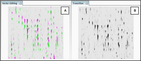
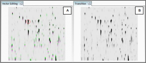
- Click on the ions shown in the current focus (orange rectangle) in Window C, this will update windows A, B and D as shown below.
- In window A click and hold the left mouse button on a green ion, it can auto align.
- If the green and magenta spot (immediately above) have not aligned automatically then drag the green ion over the magenta ion and release the mouse button.
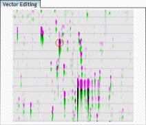
- The image will ‘bounce’ back and a red vector, starting in the green ion and finishing in the magenta ion as a circle will now appear as shown below in window A
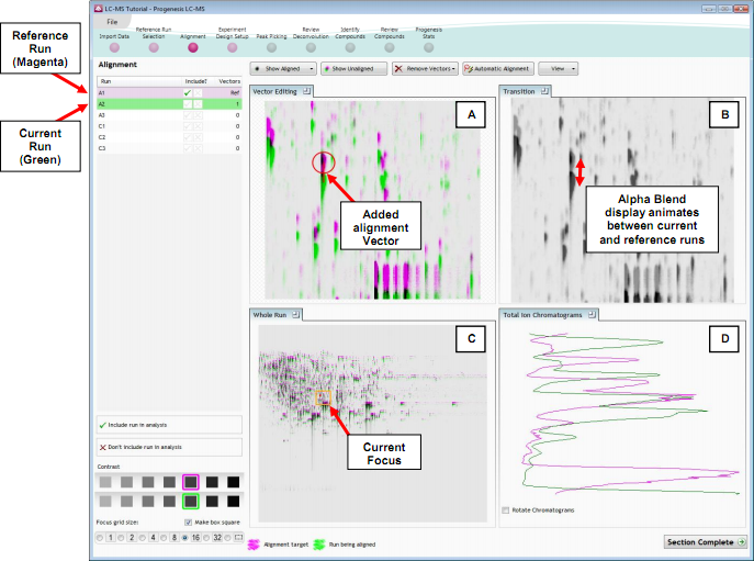
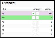
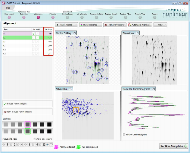
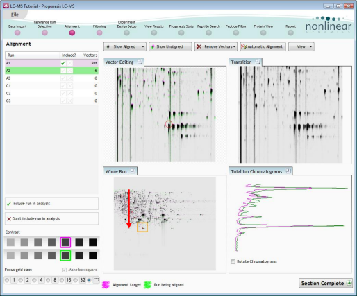
The experiment structure is displayed on the left of the screen in the Run panel based on the information you supplied at the set up stages (Import Data and Reference Run Selection).
|
Alignment: panel shows the run that is currently being aligned in green, and the run it is being aligned to in magenta. The Ref run for any experiment is the run that you chose to align all the runs to, in this case A1 highlighted in magenta. |
|
|
Vector Editing (Window A): is the main alignment area and shows the current focus rectangle as shown in Window C. The current image is displayed in green and the chosen reference image is displayed in magenta. Here is where you place the alignment vectors. Retention time alignment is performed in the vertical dimension. |
|
|
Transition (Window B): uses an alpha blend to animate between the current and reference runs. Before the runs are aligned, the ions appear to move back and forwards. After alignment, they will appear to pulse if correctly aligned. During the process of adding vectors, this view will change to show a zoomed view of the area being aligned to help accurate placement |
|
|
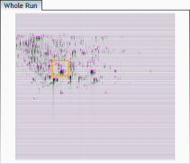
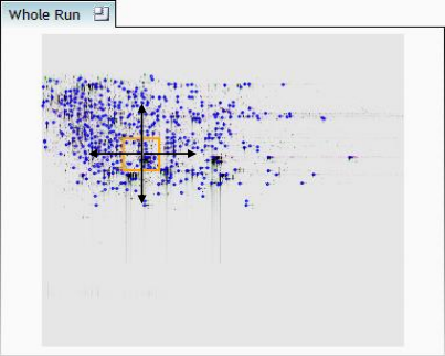
Whole Data File (Window C): shows the focus for the other windows. When you click on the view the orange rectangle will move to the selected area. The focus can be moved systematically across the view using the left and right cursor keys. The focus grid size can also be altered using the controls in the bottom left of the screen. |
|
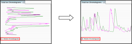
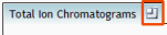
Total Ion Chromatograms (Window D): shows the current total ion chromatogram (green) overlaid on the Reference chromatogram (magenta). As the ions are aligned in the Vector Editing view (Window A) the chromatograms become aligned. The retention time range displayed is the vertical dimension of the Focus Grid currently displayed in the Whole Run view (Window C).
Note: the orientation of the TIC view can be changed according to individual preference
Note: the icon to the right of the 'Window' titles expands the view
Automatic generation of alignment vectors
The alignment of runs is required in the retention time direction; this is key to correcting for the variable elution of ions during the chromatographic separation.
The Alignment algorithm at this stage in the workflow will generate ‘Automatic’ vectors, in the retention time direction for each run, to enable the alignment of all the runs to the ‘Reference Run’ that was chosen in the previous stage of the workflow.
|
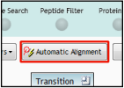
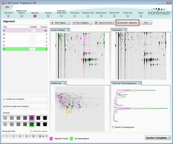
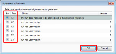
The alignment vectors are generated automatically for all the runs by using the ‘Automatic Alignment’ accessed by clicking on Automatic Alignment on the top tool bar. |
|
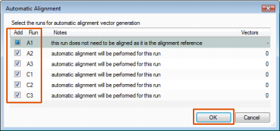
Select (tick) the runs you require to generate vectors for and click OK.
The quality of the automatic alignment can be reviewed using the various windows in the Alignment stage of the workflow. 'Blue' automatic vectors will have been added to each image with the total for each run recorded in the table to the left.
To view the alignment you can move between the Aligned and Unaligned views using the 'Show' Aligned and Unaligned buttons on the top toolbar
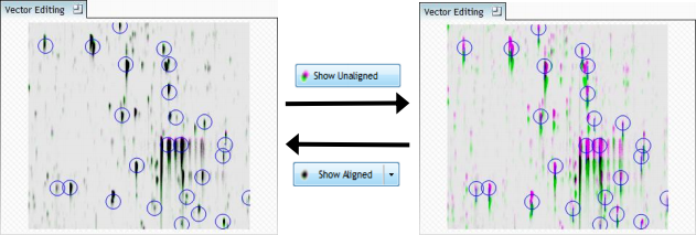
The orange 'Focus grid' in the 'Whole run' window controls how much of the 'Aligned' runs you can review in the other windows. Use the 'Arrow keys' on your keyboard to step through the alignment with an appropriate size of focus grid on the 'Whole Run' view.
If the Retention Time shift is too great for the Automatic Alignment Algorithm to pick up and/or the inter-run distortion is very high then the Automatic vectors can be removed for some or all of the alignment using the Remove Vectors tool on the top toolbar and the initial alignment can be approached manually as described in the next section
Combined Manual and Automatic Approach to alignment
To place manual alignment vectors on your current run (A2 in this example):
- Click on Run A2 in the Alignment panel, this will be highlighted in green and the reference run (A1) will be highlighted in magenta.
- You will need approximately five alignment vectors evenly distributed from top to bottom for the whole run.
- First ensure that the size of the focus area is set to 8 or Custom in the Focus grid size on
the bottom left of the screen.
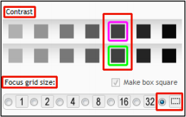
- Adjust the dual contrast to suit.
- Click on an area (see below) in the Whole Run window (C) to refocus all the windows.
Adjust Contrast as required.
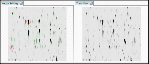
Note: the ions moving back and forwards between the 2 runs in the Transition view indicating the misalignment of the two runs - Click and hold on a green ion in Window A as shown below.
- As you are holding down the left mouse button drag the green ion over the
corresponding magenta ion of the reference image. The vector will appear as shown
below as a red circle with a ‘cross hair’ indicating that a positional lock has been found for
the overlapping ions.
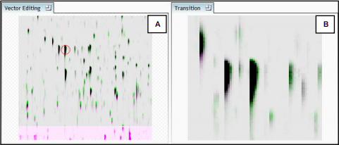
Note: as you hold down the mouse button, window B zooms in to help with the alignment - On releasing the left mouse button the image will ‘bounce’ back and a 'Red' vector, starting
in the green spot and finishing in the magenta spot will appear.
Note: an incorrectly placed vector is removed by right clicking on it in the Vector Editing window - Now click Show Aligned on the top tool bar to see the effect of adding a single vector
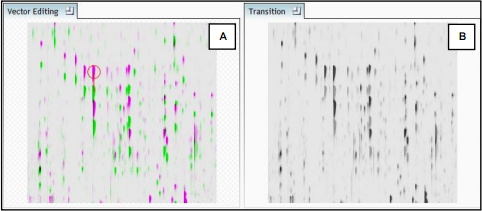
- Adding another vector will improve the alignment further. Note this time as you click to add
the vector it ‘jumps’ automatically to the correct position using the information from the
existing alignment vector
- Repeat this process moving the focus from top to bottom on the Whole Run view.
Note: the number of vectors you add is recorded in the Alignment table
- Now move on to the next run to align and repeat the addition of a few manual vectors
The number of manual vectors that you add at this stage is dependant on the misalignment between the current run and the Reference run. In a number of cases only using the Automatic vector wizard will achieve the alignment.
Also the ‘ease’ of addition of vectors is dependant on the actual differences between the runs being aligned - Repeat this process, as required, for all the runs to be aligned.
- Then select Automatic vectors and click OK.
Note: the tick boxes next to the Run name control which files to generate vectors for. On completion, the number of vectors will be updated on the Alignment panel and the Automatic vectors will appear (in blue) on the image.
If the alignment has worked well then in Windows A and C the grid lines should show minimal distortion, Window B will show ions pulsing slightly but with no movement of the ions as it moves between the images.
At this point, you should check the automatically placed (blue) vectors, as described on page 5 of this document. This will be easier with a larger grid size. Make sure the grid size is set to 4 using the ‘Focus grid size’ control at the bottom left of the window.
In each square, you can, if required add additional manual vectors, these will 'override' any existing 'auto-vectors placed in the same horizontal plane. This increases the flexibility of the alignment, especially in regions where the misalignment/distortion arising from 'atypical' chromatography appears complex.
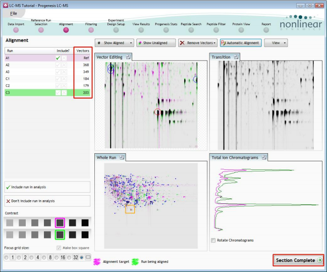
To indicate that alignment of the run is complete and ready for Analysis click Include run in analysis located underneath the image list.
Once alignment has been reviewed click Section Complete to start the Automatic Analysis of the aligned runs.